CorelDRAW to DXF: How to Export and When to Skip It
- David Schleicher

- 3 hours ago
- 7 min read
The CorelDRAW to DXF export is not hard, and in current versions it works well. Splines, Bezier curves and converted text come through cleanly. If someone told you the export mangles your artwork, that was true of older filters and is mostly a legend now.
The cost is somewhere else, and it only shows up on the second version of a job. DXF moves your geometry one way, into a program that knows nothing about your drawing. Every time the drawing changes, you pay the trip again.
This guide covers the export step by step, the version setting that actually matters, and how to decide whether the detour is worth it for the work you do.
How to export DXF from CorelDRAW
The export itself is quick. Preparing the drawing beforehand is what separates a clean DXF from one that gives your CAM program trouble.
Convert artistic text to curves with Ctrl+Q. Text entities travel badly between programs, and a font your CAM machine does not have will be substituted or dropped.
Convert outlines to objects if the outline is the part. A 2 mm outline in CorelDRAW is a display property, not geometry. On export it becomes a single centerline. If you need the shape of the outline itself, use Object then Convert Outline To Object first.
Remove fills and effects. DXF carries line work. Drop shadows, transparencies, blends and PowerClips either vanish or arrive as something you did not intend.
Delete duplicate and overlapping curves. Two curves stacked on top of each other look like one on screen and get cut twice on the machine. This is one of the most common causes of double-cut edges and doubled machining time.
Set your document units. Work in the unit your machine uses. Unit interpretation on import is inconsistent between programs, and a part that arrives at 25.4 times the intended size is almost always a unit mismatch.
File then Export (Ctrl+E). Choose AutoCAD DXF as the file type, name the file, and click Export.
Check your CorelDRAW DXF export settings. This dialog decides the version, units and text handling. The next section covers the version choice.
Verify before you machine. Re-import the DXF into a new CorelDRAW document and look at it. Two minutes here saves a scrapped workpiece.

Which DXF version should you choose?
This is the one export setting that can genuinely change what arrives on the other side.
R12 is the oldest and the most widely accepted release. If your CAM software or machine controller is old, or you do not know what it supports, R12 is the safe answer. It has one real limitation: the R12 entity set has no SPLINE entity at all. Anything the drawing stores as a spline has to be written as a polyline instead, which means straight segments.
Newer releases (2000, 2004, 2007, 2018) do include SPLINE and can carry curve data properly. Whether that helps depends entirely on the program at the other end, because plenty of CNC import filters were written against the older specification and quietly ignore what they do not recognise.
The practical rule: use the newest release your CAM program documents support for, and fall back to R12 only when something refuses to open the file. If you are stuck on R12 and your artwork is full of traced curves, expect polylines.

DXF is missing from my export list
If AutoCAD DXF does not appear in the export file type list, the filter is not installed. Not hidden, not misconfigured.
Not every CorelDRAW edition ships with the DXF and DWG filters, and reduced editions in particular may leave them out. Check Help then About to see exactly which edition and version you are running, then compare it against the feature list for that edition.
If your edition does not include the filter, you have three options: upgrade to an edition that has it, export a different format your CAM program accepts such as SVG, PDF or EPS, or generate the G-code directly from CorelDRAW and skip the file exchange entirely.
The export works. The round trip is what costs you.
Here is the part nobody counts, because each step feels small on its own.
The CorelDRAW to DXF route splits one job across two files that know nothing about each other. The drawing lives in CorelDRAW. The toolpaths, tools, depths, feeds, lead-ins and order of operations live in your CAM program. Between them sits a DXF, and it only points one way. It carries geometry forward. It carries nothing back.
So the first run is fine. You export once, set up once, cut once.
Then the customer wants the logo 15 mm wider. Or the material comes in at 19 mm instead of 18. Or a mounting hole moves.
Now the sequence is: open CorelDRAW, edit, export again, switch programs, import again, and rebuild the CAM setup, because the CAM file cannot follow your edit and the CDR has no idea toolpaths ever existed. Every tool assignment, every depth, every lead-in, in the same order as last time. On a part with a dozen operations that is not a two-minute job.

Then multiply it. A folder of near-identical variants, each with its own DXF, and after a few weeks nobody is certain which file is current. The wrong one gets cut eventually. That is not a hypothetical, it is the reason shops keep dated folders and still get it wrong.
There is a second cost that never appears in a time sheet: you are running two programs. Two interfaces, two sets of habits, two things to keep licensed and updated, and two places to look when something is off. For someone who already draws in CorelDRAW every day, that is the real price of the detour.
Count it on your own last revision. Take the most recent job where the drawing changed after you had already made the program. Measure the time between the customer asking and the machine running again. Most of that time was not drawing and it was not cutting.
Skip the export: G-code straight from CorelDRAW
If the destination is your own machine, the exchange format is a step you do not need. You can generate the G-code where the drawing already is.
CamDRAW is a CAM plugin that docks into the CorelDRAW interface. Toolpaths are set on the drawing itself. No export, no import, no second program to learn.
The part that changes your day is where the settings live. Toolpaths, tools, zero points, precision and cutting data are stored inside the CorelDRAW document. Save the CDR and everything saves with it. Reopen it next month, widen the logo, regenerate the G-code. There is no CAM setup to rebuild, no second file to keep in sync, and no question about which version is current, because there is only one file.
That is the revision loop reduced from six steps to two.

You set the precision
Curves reach the machine as straight-line moves in any CAM workflow. What matters is who decides how fine those moves are.
In CamDRAW, every operation carries its own curve precision setting, and that setting defines the segment length directly. You set it per operation, so a roughing pass in plywood and a fine engraving in brass do not have to share one resolution. Because the toolpath is calculated from the drawing itself, the precision you set holds regardless of how large or small the object is. Scale the part, regenerate, and the segment length is still the one you asked for.

What it covers
Contour machining on open and closed curves, with the tool on, inside or outside the line
Pocketing to clear internal material
Drilling at object centres, with standard drilling and retraction cycles
Engraving and cutting for milling, engraving, laser, plasma and waterjet machines
Adjustable curve precision per operation, defining the exact segment length
3D toolpath preview before anything moves
Tool and material libraries, with automatic and manual tool changes
4th axis support with G-code mapping for rotary work
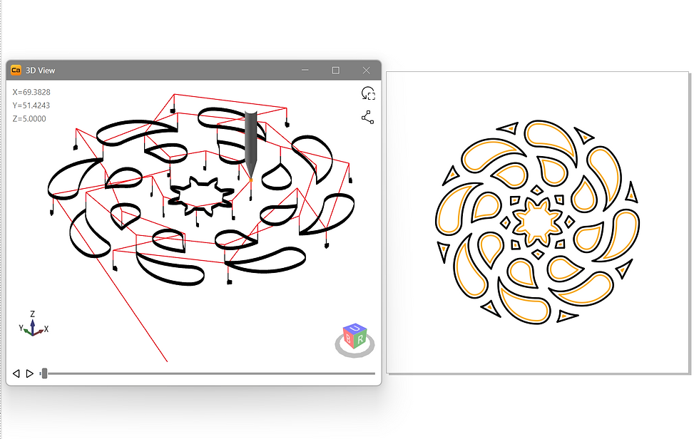
Try it on your own drawing. Download the free trial, open a file you already know, and generate a program. It runs inside the CorelDRAW you already use. If you would rather watch first, there are step-by-step tutorials.
When DXF actually is the right answer
None of this means you should stop exporting DXF. It means you should know which job you are doing. CorelDRAW to DXF earns its place the moment the file leaves your shop:
An outside supplier needs the geometry. Laser cutters, waterjet services and job shops ask for DXF, and they ask for a reason: it is the one format everyone can open.
A CAD colleague is taking it further. If your 2D profile becomes a 3D model, DXF is the handoff.
Your CAM program is fixed. If you already own a CAM package that only imports DXF, the detour is simply the workflow.
You are archiving. A neutral, documented format outlives any application version.
The distinction is simple. DXF is an exchange format. If nothing is being exchanged, you are paying for a feature you are not using.
Frequently asked questions
Is the CorelDRAW to DXF export lossy?
Much less than its reputation suggests. Current export filters handle splines, Bezier curves and converted text well. The two things that do get lost are formatting rather than geometry, fills, effects and live text, and anything the chosen DXF version cannot store. Pick the right version and the geometry arrives intact.
Why does my circle turn into hundreds of straight lines when I export to DXF?
With a current CorelDRAW version this usually does not happen. Circles and arcs have their own DXF entities, and modern export filters use them. If you are seeing dense polylines, check the version in your export options: R12 has no SPLINE entity, so curved geometry has to be written as segments. Switching to a newer release often solves it, provided your CAM program supports it.
Why is DXF missing from my CorelDRAW export list?
Your edition does not include the DXF and DWG filter. Check Help then About to confirm which edition you are running, and compare it with the feature list for that edition.
Which DXF version should I use for my CNC machine?
Use the newest release your CAM software documents support for, and drop back to R12 only if a file refuses to open. R12 is the most compatible but the most limited.
Can I convert CDR to DXF online instead?
For a one-off handoff, yes. For production work it adds an unknown: you cannot see or control how the converter handles units, scale and curve tolerance. Uploading customer artwork to a third-party service is also worth a thought.
Do I need DXF at all if I only want to run a CNC machine?
No. DXF exists to move geometry between programs. If the destination is your own machine, you can create the G-code inside CorelDRAW and skip the exchange entirely, which removes the whole export and re-setup loop from every revision.