DXF to Gcode: How to Get a Working CNC Program

Updated: Aug 23
You have a DXF file and you need G-code. That sounds like a file conversion, and plenty of tools promise exactly that.
It is not one. A DXF holds geometry: lines, arcs, circles, positions. G-code holds instructions: move here, at this speed, this deep, with this tool. Between the two sit decisions that no file contains and no software can read out of your drawing. Which line is a cut and which is an engraving. Whether the tool runs on the line, inside it, or outside it. How deep, in how many passes, in what order, and where it enters the material.
That gap is called CAM, and someone has to fill it. The only real question is who, in which program, and how much of it you have to redo the next time the drawing changes.
This guide covers the realistic ways to get from DXF to a running CNC program, what goes wrong in each of them, and how to choose.
What your DXF contains, and what your machine needs
Open a DXF in a text editor and you will find entities. A LINE has a start and an end. An ARC has a centre, a radius and two angles. A CIRCLE has a centre and a radius. That is the whole vocabulary, plus layers and colours.
Now look at what a working CNC program needs on top of that:
Which geometry gets machined at all. Drawings contain dimensions, frames, notes and construction lines. None of them should be cut.
Tool and tool diameter. Without it, no offset can be calculated.
Which side of the line. On the line, inside, or outside. This is the difference between a part that fits and a part that is undersized by the tool diameter.
Depth and passes. One pass at full depth or four passes at a quarter each.
Feed rate, spindle speed, laser or plasma power.
Lead-in and lead-out. Where the tool enters, so the pierce point does not sit on the finished edge.
Order. Which contour first, inner parts before outer ones, so nothing comes loose too early.
The right dialect. GRBL, Mach3, LinuxCNC and an industrial control all want slightly different output.
None of that is in the DXF. Every one of those decisions has to be made by you, in some program, before a machine can run anything.
DXF to gcode: the realistic options
There are three routes from DXF to gcode, and all three are legitimate depending on the job.
Online converters. Upload a DXF, set a few parameters, download a .nc file. These are the tools most people find first when they search for a DXF to gcode converter. The better ones now go well beyond simple path tracing and offer kerf compensation, lead-ins, holding tabs and multi-pass depth. For a single part on a familiar machine this is often genuinely enough, and it costs nothing.
Free desktop tools. DXF2GCODE, dxfplotter, viaConstructor and similar projects run locally, handle offsets and ordering, and are popular with plasma and router users. They ask more of you in setup and their documentation is uneven, but they are capable and they do not upload your customer's artwork anywhere.
CAM software. Fusion 360, SheetCam, CamBam and the rest. Here you get full control: tool libraries, operations, simulation, postprocessors for specific controllers. The cost is a second program to buy, learn and keep in sync with wherever your drawing actually lives.
The trap is thinking one of these is the obvious DXF to gcode answer. They differ in how much control you get and how much work each revision costs you, and those two things pull in opposite directions.
Where DXF to G-code goes wrong
Four failures account for most of the frustration with DXF to gcode conversion, and all four are avoidable once you know they exist.
The part comes out the wrong size
This is the most reported problem with every DXF to gcode tool, and it is almost never a bug. DXF stores numbers without a reliable unit header that every reader agrees on. Your drawing says 100; the receiving program decides whether that means 100 mm or 100 inches.
The symptom is unmistakable: everything is off by a factor of 25.4, or exactly ten, or the part is far outside the work area. The fix is boring and reliable. Set the unit explicitly on both sides, then measure one known dimension after import before you cut anything.
The part is undersized by exactly one tool diameter
If the toolpath runs on the line, the tool removes material on both sides of it. A pocket comes out too big, a part comes out too small, and the error is exactly the tool diameter.
This is tool radius compensation, and it is the single most common reason a first cut is scrapped. It is also the question that fills CNC forums: how do I tell the software to cut inside the circle and outside the square. Any tool worth using lets you choose centre, inside or outside per contour. If yours does not, that is a reason to change tools, not a setting you have missed.
The machining order is wrong
Converters typically follow the order the geometry appears in the file, which is the order it happened to be drawn. That means inner cutouts can be cut after the outer contour, so the part is already loose when the last cuts happen. On sheet material the result moves, and the cut wanders.
You want either automatic optimisation by shortest path with inner contours first, or explicit manual control. Automatic ordering with no way to override it is the worst of both.
The pierce point sits on the finished edge
On plasma and laser work, starting the cut directly on the contour leaves a mark exactly where the part is visible. Lead-ins and lead-outs move the entry off the finished edge, tangentially or at an angle. Many simple converters skip them entirely, and on a router the equivalent problem is a plunge mark at the start of every contour.
If your drawing already lives in CorelDRAW
One thing first, so you do not waste your time: this section only helps if you have CorelDRAW. CamDRAW is a plugin for it, not a standalone converter. If you work in Inkscape, LibreCAD or Fusion, one of the routes above is your answer and you can skip ahead.
If you do have CorelDRAW, there are two cases, and both end in the same place.
You drew it yourself. Then the DXF never has to exist. Set the operations on your drawing and generate the program.
The DXF came from someone else. Import it into CorelDRAW, then set the operations on the imported curves. Same result, one program instead of two, and you get CorelDRAW's editing tools on the way in, which matters more than it sounds. Received drawings arrive with dimension lines, frames and construction geometry that must not be cut, with duplicate curves stacked on top of each other, and with contours that look closed and are not. Cleaning that up before machining is a drawing job, and you are already in a drawing program.
Either way, the DXF stops being a step in your process and becomes what it always was: a file you received once. Save the job as a CDR with its operations, and the repeat order in three months is an open and a click, instead of starting the conversion again from nothing.
CamDRAW docks into the CorelDRAW interface. You select drawing objects, assign machining operations, and generate the program. Whatever the geometry's origin, from there on it is one program: no export back out, no round trip between two applications, and no second setup to rebuild the next time the drawing changes.
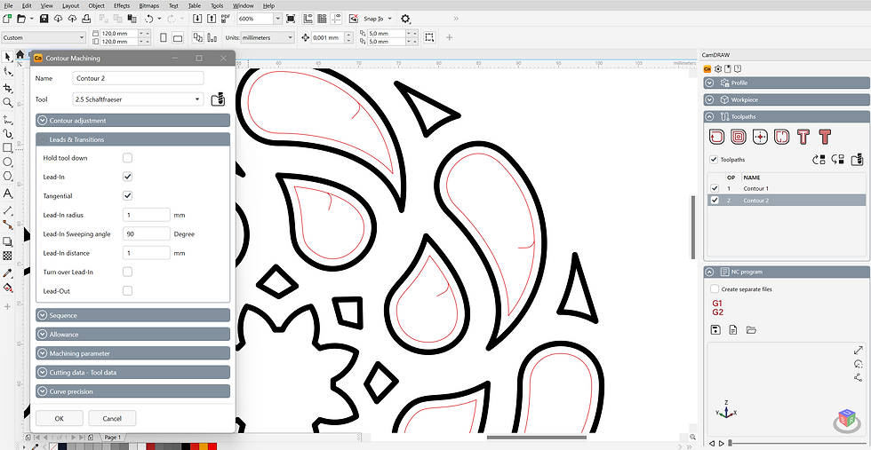
Every decision from the list at the top of this article is made in one dialog per operation:

Contour machining on open and closed curves, with the tool on, inside or outside the line, and the tool radius applied from the tool library
Pocketing to clear material inside closed contours, sorted from the inside out
Drilling at object centres with several retraction cycles
Contour cutting for plasma, laser and waterjet, with the cut on and off commands written by the postprocessor
Lead-ins and lead-outs, linear or tangential, set separately from each other
Material tabs so parts stay fixed in the sheet until the job finishes
Order control, either optimised by shortest path or exactly as the objects sit on the layer
Adjustable curve precision per operation, defining the segment length directly
The part that matters on the second version
All of it is stored inside the CorelDRAW document. Operations, tools, zero points, cutting data and precision are written into the CDR when you save. Reopen the file next month, change the drawing, regenerate the program. Nothing to rebuild, no second file to keep in sync, and no doubt about which version is current, because there is only one file.
That is the criterion from the introduction. Not what a tool can do once, but what it costs the fifth time the customer changes something.

Postprocessors for common controllers are included, GRBL, Mach3, LinuxCNC, EdingCNC, Estlcam, Langmuir CrossFire and many more, and they can be edited to match your machine. CorelDRAW X7 through the current release is supported, including the Standard, Essentials and Special editions. Check the specifications if you are unsure about your version.

Try it on a drawing you already know. Start the free trial, set two operations, and generate a program. It runs inside the CorelDRAW you already have. There are also step-by-step tutorials if you would rather watch first.
When a converter is the right answer
Plenty of the time it is.
It is a one-off. A single part, cut once, never revised. Setup time is the only cost that matters and a converter wins on that.
You do not use CorelDRAW. Then the question is simply which converter or CAM program fits your machine and your patience.
Your workflow is already settled. If Fusion or SheetCam is doing the job and everyone knows it, changing it costs more than it saves.
The distinction that actually matters is not free against paid. It is whether the job will come back. Cut it once and forget it, and a converter is the efficient answer. Cut it again in three months with a change, and every minute spent rebuilding the setup is a minute you will spend again.
Frequently asked questions
Is there a free DXF to gcode converter?
Yes, several. Browser-based converters handle simple jobs without installation, and desktop projects such as DXF2GCODE and dxfplotter run locally and support offsets, tabs and ordering. Free is a real option for straightforward parts. What you trade away is control over edge cases and, usually, any connection back to the drawing.
How do I convert DXF to gcode for my machine?
Pick the route that matches how often the job will come back, then set four things in whichever tool you choose: the unit, the tool diameter, which side of the line the tool runs on, and the depth or number of passes. Generate the program, then simulate or preview it before the machine touches material. If you already own CorelDRAW, you can skip the file step and set the operations on the drawing itself, imported DXF included.
Why is my converted part the wrong size?
Almost always units. DXF does not carry a unit declaration that every reader interprets the same way, so a drawing exported in millimetres can be read as inches. Set units explicitly in the converter and measure one known dimension after import before cutting.
Why is my cut part smaller than the drawing?
The toolpath is running on the line instead of outside it, so the tool removes material from the part. The error equals the tool diameter. Set the contour to outside for parts and inside for holes, and make sure the correct tool diameter is stored.
Can I convert DXF to G-code without CAM software?
You can produce G-code without a full CAM package, but you cannot skip the CAM decisions. Every converter asks you for them in some form, even if it only offers feed rate and depth. The question is how many of those decisions the tool exposes and how many it silently makes for you.
Which DXF to gcode converter is best for plasma cutting?
For plasma the two features that matter most are lead-ins and kerf compensation. Starting the cut on the contour leaves a pierce mark on the finished edge, and cutting on the line makes every part undersized by the kerf width. Any DXF to gcode tool you consider for plasma should let you set both, plus cutting order so inner shapes are cut before the outer contour.
Do I need to export DXF at all?
Only if the geometry has to move between programs. If you draw in CorelDRAW and cut on your own machine, you can generate the G-code inside CorelDRAW and the DXF step disappears, along with the unit checks and the re-setup on every revision. Related reading: exporting DXF from CorelDRAW and exporting SVG from CorelDRAW.

